...Return To Mine & Other Bonneville Car Construction Pages
.Previous Page...............B'ville Car Index Page.........................Next Page
............................................ Front Axles --- Part I
............... .
.
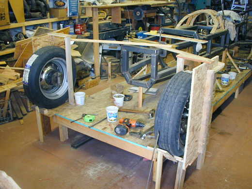
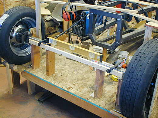
On the last page I had the left front tire/spindle mounted in line with the left rear tire. Here I have also located the right front tire/spindle and I'm ready to start construction of the two front axles. They will be similar to Ford's twin I-beam setup.
................... .
.
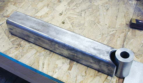
I'll build these axles in stages as they will both be offset so they can pass by each other in the middle of the car. I started with 3/16 X 2 inch X 12 inch long square tubing. I notched the end at an angle for the bosses I had made earlier ( on this page ). The first one I notched by grinding it out with the hand grinder. Then I got smarter and remembered I had a mill. One end of the square tubing is cut square and the other end is cut to the same angle as the king pin angle. I then put the round boss on each side and marked the outline with a fine tip marker and proceeded to get close to that line with the mill. I finished it up with the hand grinder. That went a lot quicker.
............... ....................
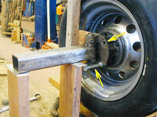
With the wheel/tire set to zero degrees camber I leveled the first part of the axle with shims and welded it to the boss that was back on the spindle with the king pin in place. I just tacked it. The lower arrow points to a bolt in the spindle back. I also had one in the hole at the upper arrow. I used these and a level to get the king pin/spindle straight up and down (zero caster) at this point while I welded the axle end to the boss.
............................ .
.
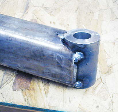
Here is one end tacked together. I have a 175 amp 220 mig and worried about getting good penetration into the heavy boss, so I'll take this to a local welder and have him finish welding this part. I don't want a failure of this critical piece.
.................
Here I'm getting ready to pull the wheel/tires and put them back into storage. I have a piece of wood clamped to the short axle pieces to help hold everything in place as I remove the wheels.
..................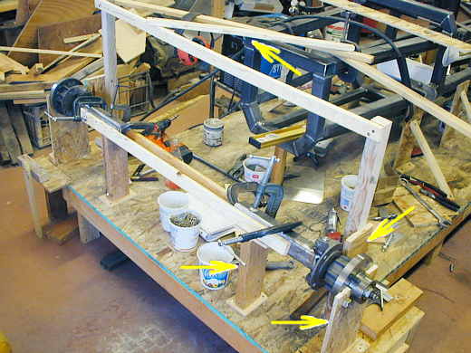
Before removing the wheels I added some top bracing (upper arrow) and the spindle backs are clamped to uprights (right side arrow). I have also cut the axle supports (bottom left arrow) at a 18 degree angle and rotated the short axle pieces to that 18 degrees, which will be my final "castor" angle. After I did all of that and made sure everything would remain in place I pulled the wheels/tires off and made uprights (very bottom arrow) that screw to the table and bolt to the hubs where the wheels were. These hold the hubs in the same position as if the wheels were in place. Doing all of this locating with wood pieces and the wood table goes very quickly (probably about 45 minutes) and lets me locate things where I want them with ease. A metal table/surface plate is probably stiffer and more durable if you were doing repeated building on it. but for a home builder this wood table can't be beat. I saw a friend in Phoenix building a very custom (all homemade frame and suspension) street rod on one a number of years ago and it stuck in my mind as a good thing to do. I've been thankful many times I went to his house that day.
..................................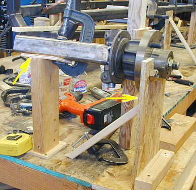
Here is a close-up showing the left side at this point. You can see how the axle/spindle are rotated 18 degrees and held at that angle by the support (left arrow). You can also see the hub support more clearly (right arrow).
..........................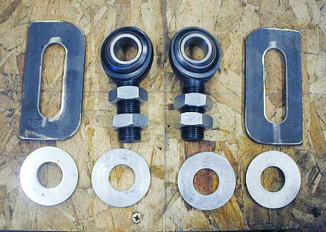
To finish the axles I wanted to locate the other ends of them. They will have a 3/4 inch rod end on their ends. The rod end will slide up in down in the slotted brackets to set the final camber. I made the brackets from 3/16 X 2 inch strap. I put the slots in them with the mill and decreased the outside diameter of the 3/4 inch washers with the lathe so that they were less than 2 inches in diameter.
..........................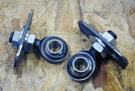
Here you can see the brackets with the rod ends in them. The brackets will be attached to a cross-member in the car and will have more reinforcing built into them later.
...................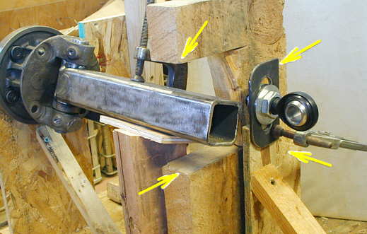
Here you can see the bracket/rod end (top right arrow) that will be the end of the left axle mounted to an upright (bottom right arrow). The big wood block with the "C" shaped cutout tells me where the top of the pod (top left arrow) that will cover the suspension/axles will be and where the bottom of the pod (bottom left arrow) that will cover the suspension/axles will be. The axle and suspension will operate within that 5 inch area. To help the aerodynamics of the car the pod will cover these components in the front and continue down the sides of the car and cover the rear suspension and axles. Between the front and rear of the car the pods (both sides of the car) will house the water for motor cooling on one side and ice water for the intercooler on the other side along with probably the fire bottles.
...................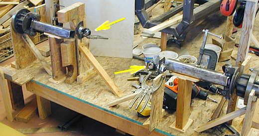
Here you can see both of the rod ends located that will attach to the ends of each axle. The axles will have a step in them in the middles so that they can pass by each other. Now the next step is to finish the axles.
..................................................................Next Page